Poor Man's Spectrum Analyser, 0–150 (450) MHz
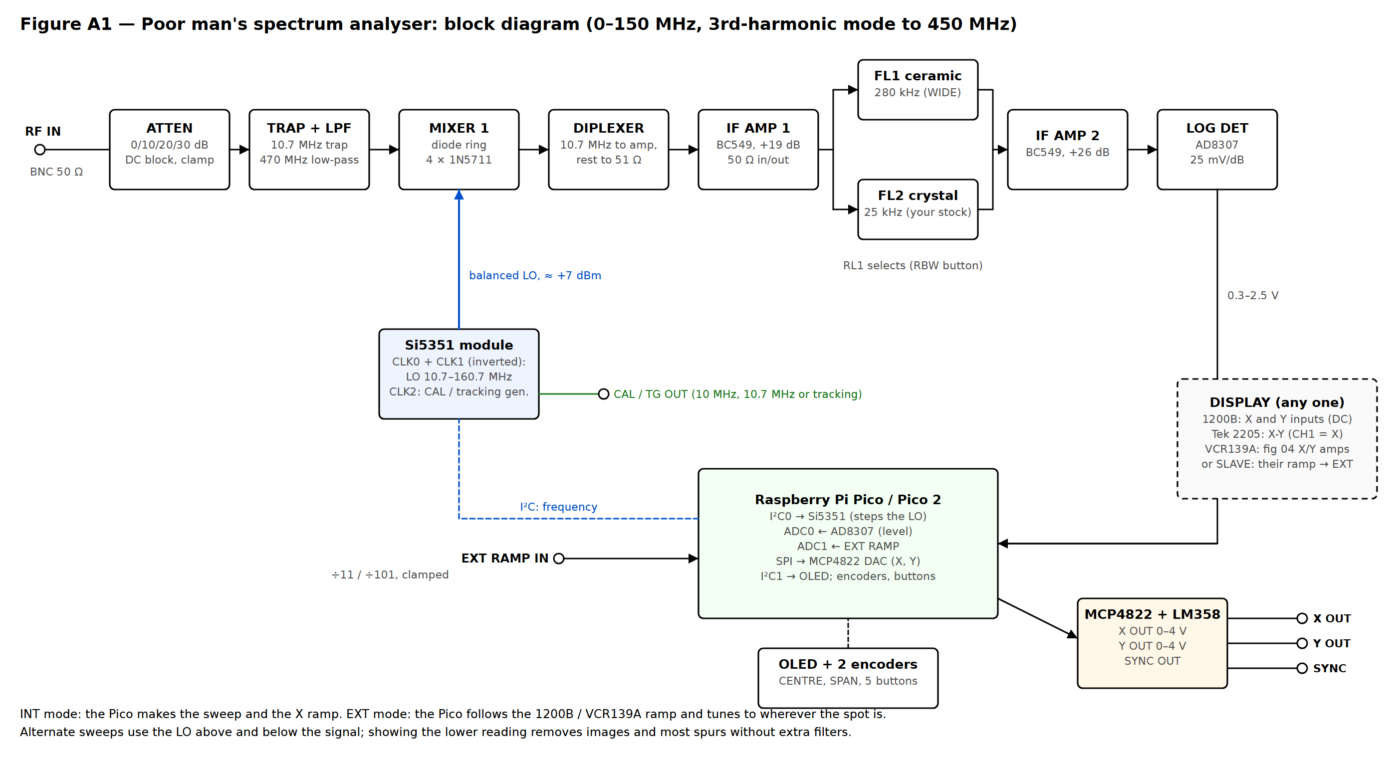
A spectrum analyser is the one instrument most workshops go without. This box makes one from a £3 Si5351 clock module, a home-made diode-ring mixer, a 10.7 MHz IF from FM-radio parts, an AD8307 log detector and a Raspberry Pi Pico. Any scope with X and Y inputs is the display.
It can make its own sweep, or follow the time base of the scope it is plugged into, even the curved sawtooth of a 1950s gas-triode time base. Images and spurs are removed in software by sweeping with the oscillator above and then below the signal, and the oscillator's third harmonic stretches the range to 450 MHz.
Revision 2 adds a tracking generator at no extra cost: the clock chip's spare output follows the analyser's tuning, so a filter placed between them shows its frequency response directly on the screen.
At a glance
| Range | 0–150 MHz; 150–450 MHz on the 3rd harmonic |
|---|---|
| Resolution | 280 kHz or 25 kHz |
| Display | 80 dB, 10 dB/div; level readout in dBm |
| Tracking generator | 10 kHz–150 MHz, normalised display |
| Displays | 1200B, Tektronix 2205 (X-Y), VCR139A |
| Status | Design |
Block diagram
Click a drawing to open it full size.
Documentation
The full design report, schematics and parts list will be published here once the project has been built, tested and filmed.